Inventor Design Automation Guidelines
Wesley Zloza | Mar 4, 2025 | 16 min read
As an engineer with over 15 years of experience, I’ve had the privilege of working on a wide variety of design automation projects utilizing iLogic and the Inventor API. Throughout this time I’ve developed a series of best practices (i.e., my guidelines) for working with CAD models and writing iLogic.
Contents
Modeling
- Top-down modeling such as skeleton modeling and/or multi-body modeling should be avoided on parts and assemblies used as master models.1 This modeling approach is appealing because it allows users to quickly develop complex parametrically controlled designs. These designs, however, can be difficult to manage programmatically because of the number of references that get created between the components. As a result, it generally recommended that parts be configured explicitly and not driven from a top level assembly or sketch.
- Adaptive parts and assemblies should also be avoided in master models used for CAD automation.
Parameters
Parameters are a set intrinsic variables that define the size, shape, and/or functionality of a part and/or assembly. Autodesk Inventor has three types of parameters:
- model parameters,
- reference parameters,
- and user parameters.
Only user parameters should be programmatically driven when performing CAD automation. Model parameters and reference parameters (in most cases) should be left untouched for the following reasons:
- Model parameters are automatically created and deleted with the addition and removal of part features and constraints. These generated values are intended to be consumed by a single entity. A user can reference a model parameter within another feature, however, this is strongly discouraged as it makes the model harder to manage and can lead to “spaghetti references”.
- Model and reference parameters are named sequentially by default. Because of this behavior they provide no context to the modeler/user as they navigate the Parameters Window. This is especially true when the “Consumed by” features and/or parameters also do not have descriptive names. In order to improve the navigation a user would be required to manually overwrite these names or add comments.
- Model and reference parameters always use the units of measure (UOM) defined by the document. In addition, model and reference parameters are always a length or angular measurement.
Overall, user parameters are a more stable and have a greater range of features. These parameters can have units of measure separate from the document, they do not have be consumed by a feature to exist (i.e., they can exist in an empty part or assembly), they can be driven by a Microsoft Excel spreadsheet, and they can have different types: a number, string, or boolean. More information about parameters is provided in the official Autodesk documentation.
Parameter Guidelines
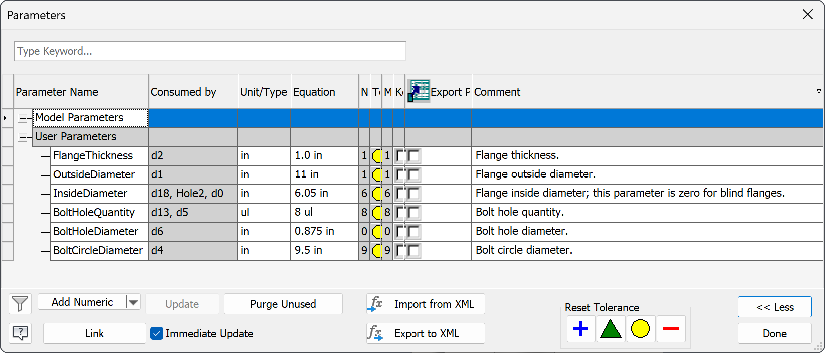
- A user parameter should be created for each critical dimension and design feature. The name of each user parameter should be descriptive and written in PascalCase.2 Each user parameter should contain a comment that further clarifies its meaning; comments should be written in full sentences. It is recommended that user parameters use the same unit of measures defined in the document, however, this is not strictly required. These guidelines are illustrated in Figure 1 and Figure 2 (shown below) where the parameters window for a basic flange model is shown.
- Equations are permitted inside parameters but they should be used with caution. Avoid creating verbose equations or deeply nested operations. iLogic or the Inventor API should be used in situations where complex math is required. Refer to the Autodesk Inventor documentation for a reference of functions, prefixes, and algebraic operations.
- Model parameters should be edited with caution from the Parameters Window. Only in rare cases should it be necessary to rename a model parameter from its default value. A model parameter should never be directly driven from iLogic or the Inventor API.
- Reference parameters, if necessary, should be renamed from their sequential default value. Reference parameters should follow the same naming convention as user parameters.

Work Features
Properly defined work features are key to creating robust and stable models for use in CAD automation. It is important that when creating work features that their location be strictly defined using global geometry and user parameters. A named entity can be used in place of work feature if this cannot be easily achieved. The following rules should be applied when working with work features:
- Work features should be given descriptive unique names. Each name should be in Capitalized Sentence Case (i.e., each word in the name should be capitalized and delimited with a space).3
- Work features should be created for each constraint that will be required in a parent assembly. For example, a model of a flange should contain work features for its mating face and the horizontal and vertical centerline (unless the global planes already align with this geometry).
Named Entities
Named entities (otherwise referred to as named geometry) can be used for drawing
automation and in assemblies where work features would otherwise be tedious to
create. Named entities, however, should be used with caution. Because named
entities are tied to geometry, it is possible for them to be removed by the
modification or deletion of a part feature. Named entities should be given a
name that indicate its type and location and written in PascalCase.4 For
example, an appropriate name of corner on a plate would be “VertexTopRight”. The
available geometry types are Vertex, Edge, and Face.
Model Tree
The model tree displays different content depending on the document type. In a part file, for example, the model tree will display part features and sketches while in assembly it will display component occurrences. The default naming convention used by Autodesk Inventor also varies based on the node type. The following rules should be followed when creating nodes in the model tree:
Part Model Tree
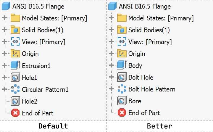
- Each critical feature and sketch in a part should be renamed from its default value and given a descriptive unique name in Capitalized Sentence Case.3 A critical feature is any node in the model tree that is parametrically driven or must be identified programmatically.
Assembly Model Tree
- Each item in the model tree should be renamed from its default value and given a descriptive unique name in Capitalized Sentence Case.3 Renaming each occurrence in the model tree ensures that they can be easily be identified by a user and that they can be queried using iLogic and/or the Inventor API.
- Identical occurrences should be numbered sequentially or given a suffix that clarifies its application or location. For example, the names “Plate - 1” and “Plate - 2” or “Plate - Top” and “Plate - Bottom” are good occurrence names.
- Folders should be used to group occurrences by type, location, or function. Top level hardware (bolts, washers, nuts, ect.) should be placed in a folder labeled “Hardware”.
Drawing Model Tree
- Views and sketches should be given a descriptive unique name in Capitalized Sentence Case.3
iProperties
iProperties define the identity of a part, assembly, and/or drawing. The following list only covers the minimum requirements/best practices when working with this data:
- The
Titlefield should always be defined. The title should be descriptive but concise. For example, consider the following title for a bolt: “HHCS 1/4”-20 UNC X 5.00”, ASTM A449”. From this title one knows the bolt type (hex head cap screw), the thread type, the length, and its design specification. - The
Descriptionfield should contain additional data that would be too verbose to include in theTitle. - The
Subjectfield should be used to group parts and assemblies based on their or product group. Custom iProperties should be used in lieu of theSubjectfield if a fine level of granularity is required. - All parts should have the correct material assigned. The “Generic” material material type should be avoided at all costs as it likely won’t provide the correct physical properties.
- Parts and assemblies created via CAD automation:
- Should have the
Revisionfield explicitly defined as “0” (or “A” if using an alphabetic system). - Should have the
AuthorandDesignerfields filled with a provided user name or using the user name defined in application options (i.e.,ThisApplication.UserName).
- Should have the
File Naming
Companies have various rules/opinions regarding file naming. In most cases, companies will choose to name CAD files based on their associated part number.5 This practice works well as long as the following exception is made - a part number (or autogenerated file name) should not be assigned to files used in CAD automation. These files instead should be given descriptive names and organized based on their scope (similar to a namespace).
iLogic
iLogic embeds rules as objects directly into part, assembly, and drawing documents. Typically, the rules that are defined by the user are used to determine the design of a model and drive the content inside a document. iLogic should be used for simple automation; the Inventor API should be used instead if any of the following conditions apply:6
- iLogic should not be used if code must be reused across rules or documents. Copying and pasting code across rules indicates that an encapsulation of logic is necessary. In this case a class library (i.e., a dll/assembly) should be written and included as a reference. However, this leads into the following bullet point.
- iLogic should not be used if references to other libraries are necessary. Although iLogic has the ability to reference other assemblies, their location and distribution can not be guaranteed across users. A reference to a missing library will result in the iLogic rule to fail and poor user acceptance.
- iLogic should not be used if a large amount of design and engineering calculations need to be performed. These calculations often need to be performed multiple times throughout the life of a project and included in reports such as sales proposals and engineering submittals. These calculations would need to be copied from there original source or referenced by the rule in order to be invoked; thus violating the previous two bullet points.
- iLogic should not be used if manipulation of a large number of parts and/or assemblies are necessary. In general, iLogic should only be used to modify the active document. Thus, it would only be applicable for assemblies that are configured to order (CTO) or parts.
General
-
Code should be written in a way that maximizes readability. Limit lines to 80 characters whenever possible, however, this is not a strict requirement. Lines can be longer than 80 characters if it makes the code easier to read/understand.
-
All blocks/scopes (i.e., conditions, functions, subroutines, etc.) should be indented.
' 👎 Bad
If length < 0 Then
response = "Invalid length provided."
Else
response = "Looks good!"
End If

' 👍 Good
If length < 0 Then
  response = "Invalid length provided."
Else
  response = "Looks good!"
End If
Rules
- Rules should be assigned a name in Capital Sentence Case.
- A single rule should be used as the primary entry point for an iLogic configurator. All other rules should be invoked from this main rule.
- Rules should be invoked explicitly using a button (either in a form or in the iLogic Browser) or by right clicking on the rule and selecting “Run Rule”.
- Event triggers should be avoided; only in rare cases should they be acceptable. The use of event triggers, especially the “Any Model Parameter Change” trigger, can cause unexpected behavior in the order of operations of computed code and unintentionally produce a race condition. The “After Save Document” event trigger should never be used.
- Rules should be treated as namespaces; classes, functions, and subroutines should be grouped together by their intended function. Note that rules can only reference other rules by invoking them and that objects inside rules cannot be accessed.
Comments
-
Start all comments with a space to make it easier to read.
-
Comments should be clear and full sentences. Explain anything that doesn’t make immediate sense.
-
Prefixing your comments with
FIXMEorTODOhelps other developers and reviewers quickly understand if you’re pointing out a problem that needs to be revisited, or if you’re suggesting a solution to the problem that needs to be implemented. These are different than regular comments because they are actionable. -
Add a newline above a comment when the previous code is on same indention level. Otherwise, don’t have a line break.
' 👎 Bad
Private Sub doSomething()

  ' Different indention from line above, no need for newline above.
  Application.ScreenUpdating = False
  ' Same indention as previous code, must add a newline above to make it easy to read.
  Application.ScreenUpdating = True
End Sub

' 👍 Good
Private Sub doSomething()
  ' Different indention from line above, no new line.
  Application.ScreenUpdating = False

  ' Same indention as previous code, add a newline above.
  Application.ScreenUpdating = True
End Sub
Variables
-
The explicit options should enabled. This ensures all variables are explicitly declared.
Option Explicit On Sub Main() plateWidth = 4 ' Compile error; variable not declared. End Sub -
Variable names should be descriptive and the use of abbreviations should be kept to a minimum. Single letter variables are only acceptable in for-loops, however, more descriptive variables such as
indexare preferred.' 👎 Bad Dim w As Double Dim l As Double Dim dx As Double Dim dia As Double ' 👍 Good Dim width As Double Dim length As Double Dim holeSpacing AS Double Dim holeDiameter As Double -
Use one
Dimdeclaration per variable or assignment. Why? It’s easier to read and debug. This also prevents variables from accidentally being declared asVariants.' 👎 Invalid; plateWidth is a Variant, NOT a Double Dim plateWidth, plateThickness As Double ' 👎 Bad Dim plateWidth As Double, plateThickness As Double ' 👍 Good Dim plateWidth As Double Dim plateThickness As Double -
Declare variable types explicitly.
' 👎 Bad Dim plateWidth Dim plateDescription Dim plateDocument ' 👍 Good Dim plateWidth As Double Dim plateDescription As String Dim plateDocument As PartDocument -
Name local variables in camel case (camelCase). Keep acronyms like HTTP, RFC, and XML in uppercase.
' 👎 Bad Dim engineer_name As String Dim engineername As String Dim projectXml As String ' 👍 Good Dim engineerName As String Dim projectXML As String -
Name global variables in upper snake case (UPPERCASE_SNAKE_CASE). Global variables should be declared at the top of an iLogic rule and defined in succession.
' 👎 Bad Dim error_message As String Dim errorMessage As String Dim CLIENTID As String Dim HTTPAddress As String ' 👍 Good Dim ERROR_MESSAGE As String Dim CLIENT_ID As String Dim HTTP_ADDRESS As String -
Name types and classes in pascal case (PascalCase).
' 👍 Good ''' <summary> ''' Represents a two dimensional (2D) point. ''' </summary> Class Point ''' <summary> ''' Horizontal (X) location in inches. ''' </summary> Public Property X As Double ''' <summary> ''' Vertical (Y) location in inches. ''' </summary> Public Property Y As Double ''' <summary> ''' Creates a new instance of a two dimensional (2D) point. ''' </summary> Public Sub New() X = 0: Y = 0 End Sub End Class -
Unused variables should be removed. Variables that are declared but never used are likely an error from incomplete refactoring. Unused variables cause “noise” in a codebase, can reduce performance, and can cause confusion in collaborators and reviewers.
Functions
-
Functions should perform a single action and comply with the single responsibility principle.
-
Functions should not mutate an object unless necessary and explicitly noted within a comment.
-
Functions should have a descriptive name and should be prefixed with verb that describes the operation that is performed. The verbs “get”, “calculate”, “add”, and “remove” are common prefixes that can be used.
' 👎 Bad ' The function name, although descriptive, does not indicate what operation is ' being performed. In this example the argument name could also be more ' descriptive. Function weight(part As PartDocument) part.Update Return part.ComponentDefinition.MassProperties.Mass End Function ' 👍 Good ' The function name is descriptive and contains a verb that indicates the ' operation performed when invoked. The argument name is also descriptive and ' further conveys its type. Function calculatePartWeight(partDocument As PartDocument) partDocument.Update Return partDocument.ComponentDefinition.MassProperties.Mass End Function -
Public functions should be commented using XML comment specification. Refer to official Microsoft documentation for more information.
''' <summary>
''' Adds two numbers together.
''' </summary>
''' <param name="number1>First number.<param>
''' <param name="number2">Second number.<param>
''' <returns>The sum of the first and second number.</returns>
Function add(number1 As Double, number2 As Double) As Double
  add = number1 + number2
End Function
Footnotes
-
A master model may also be referred to as a template or factory file. These files are never directly used for fabrication; instead but is used by an automation program as a starter to generate models that will be used in fabrication. ↩
-
It is recommended to use PascalCase when naming parameters because this is consistent with the naming conventions used in C#. ↩
-
Capitalized Sentence Case is recommend because it easier to read. Some may argue, however, that this naming convention is more prone to error especially when names are used programmatically to get a reference of an object. For example, one of the most frustrating issues is to debug is failing to find a reference of an object because an extra space was accidentally included between a word. If this is a concern, then PascalCase can be as a substitute. ↩ ↩2 ↩3 ↩4
-
Readers will notice that PascalCase is recommended for parameters and named entities while Capitalized Sentence Case is recommended for part features, assembly features, work features, and sketches (i.e., objects shown in the model tree). This differentiation was based on who is consuming these objects. Parameters and named entities are mostly utilized by advanced CAD users while the other objects are consumed by users of all skill types. As a result, it felt important for the items in the model tree to have higher readability. ↩
-
Companies not using a document management system (DMS) generally depend on this practice because its the only way they can quickly locate part models and drawings in the file system. ↩
-
The Autodesk Inventor API (or more specifically .NET) is preferred over iLogic. Although the learning curve associated with the API is higher, it is easier to maintain, it allows for better collaboration between users, and it promotes the re-use of code. ↩